APM FEM
APM FEM
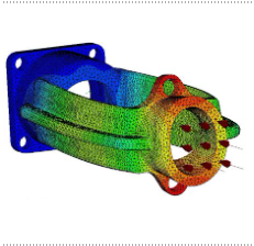
The APM FEM application is designed to perform express calculations of solid objects in the KOMPAS-3D system and visualize the results of these calculations.
APM FEM includes tools for preparing parts and assemblies for analysis, setting boundary conditions and loads, as well as built-in finite element mesh generators (both with constant and variable step) and a postprocessor. This functional set allows you to simulate a solid object and comprehensively analyze the behavior of the calculation model under various influences in terms of statics, natural frequencies, stability and thermal loading.
To create a finite element representation of an object, APM FEM provides a function for generating a FE mesh, when called, the corresponding partition of the object with a given step occurs. If the created computational model has complex non-uniform geometric transitions, then the so-called adaptive partitioning can be carried out. In order to improve the quality of the result of the process, the FE mesh generator automatically (taking into account the maximum thickening factor specified by the user) varies the size of the partition step.
The strength analysis of the APM FEM module allows solving linear problems:
- stress-strain state (static calculation);
- static strength of assemblies;
- sustainability;
- thermoelasticity;
- stationary heat conduction.
Dynamic analysis allows you to determine the frequencies and forms of natural oscillations, including for models with preloading.
The calculation results are:
- distribution of equivalent stresses and their components, as well as principal stresses;
- distribution of linear, angular and total movements;
- distribution of deformations by model elements;
- maps and diagrams of the distribution of internal forces;
- the value of the stability factor and the form of stability loss;
- distribution of safety factors and the number of cycles according to the criterion of fatigue strength;
- distribution of safety factors according to the criteria of fluidity and strength;
- distribution of temperature fields and thermal stresses;
- coordinates of the center of gravity, weight, volume, length, surface area, moments of inertia of the model, as well as moments of inertia, static moments and cross-sectional areas;
- reactions in the supports of the structure, as well as the total reactions reduced to the center of gravity of the model.
Requires for work: KOMPAS-3D