Technology: TX
Technology: TX
The application is designed to automate the release of design documentation for the “Production Technology” section for industrial facilities, process plants and process industries.
Implements the requirements of GOST 21.401-88 “SPDS. Production technology. Basic requirements for working drawings” and GOST 21.606-95 “SPDS. Rules for the implementation of working documentation for thermal and mechanical solutions for boiler houses.
The application interface is focused on quick learning, convenient and efficient use, significantly reducing the time for creating working documentation.
The application tools solve a number of designer’s tasks: creating a process flow diagram, designing process piping, and arranging equipment on plans and sections of buildings and structures.
The application is based on the principle of MinD intelligent building design technology. Obtaining sections, specifications, axonometric diagrams in automatic mode and in the mode of two-dimensional object-oriented technology leads to an acceleration of the design process.
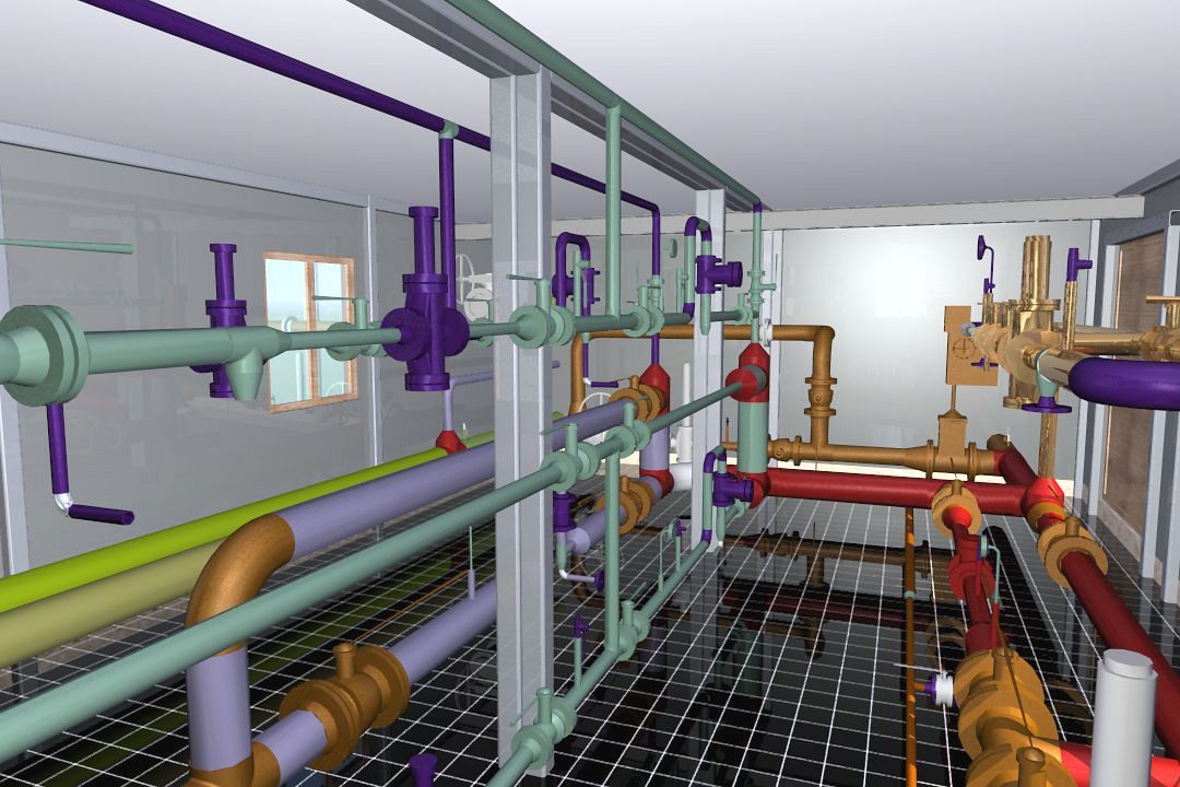
The use of the construction object manager in the work will allow you to create floors and levels of multi-storey buildings, manage floor parameters and automatically generate three-dimensional models of objects, which will allow you to visually control the design decisions made.
WORK TOGETHER WITH THE PRODUCT
Architecture : AS / AR _ _ _ _
The application tools were created based on the tasks of the designers.
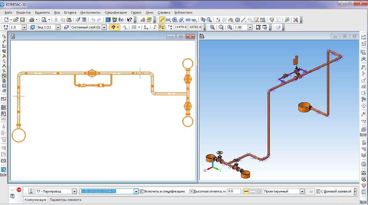
Creation of a principal (functional) technological scheme
To solve this problem, the designer can use all the available elements of equipment and pipes in a simplified (schematic) display. At the same time, each selected element remains “intelligent” and stores a large number of properties and characteristics. This allows you to automatically get a specification on the drawing sheet after the creation of the scheme.
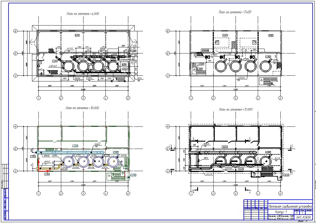
Design of technological piping and arrangement of equipment on plans and sections of buildings and structures
This task is solved using the same equipment and pipes in the detailed view and the desired projection. In this case, the designer gets the opportunity to take into account the height marks of equipment, pipelines and fittings. The application automatically calculates the length of the pipes and takes into account whether the equipment belongs to production lines (the number of lines is determined in the settings). The designer, after placing the equipment in the design position, proceeds to tie them with communications in the following ways:
- Determine the communication routes, characteristic sections (turns, branches), install fittings (bends, tees, etc.) along the routes, and then connect all the elements with pipes.
- Lay the pipes taking into account the necessary turns, and then install fittings (bends, tees, etc.) with a tie-in. At the tie-in points, the necessary part of the pipe is automatically removed.
The application’s tools offer assistance when laying pipelines along walls or existing utilities. To do this, it is possible to build communication sections with a specified indent from the cursor.
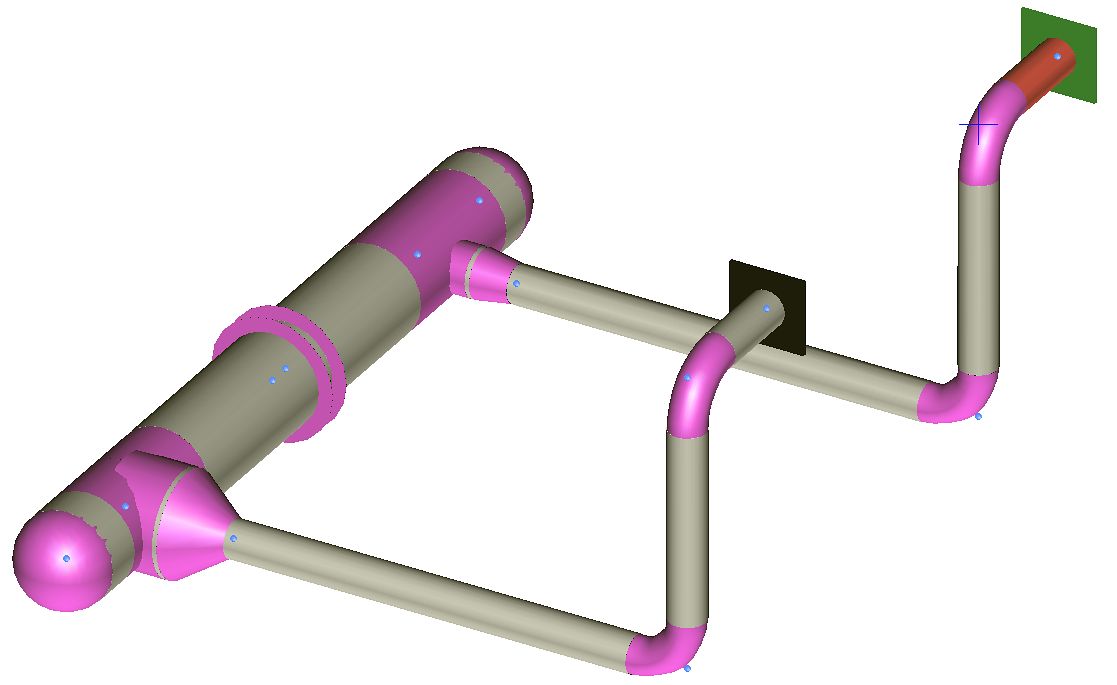
Arrangement of fittings (with insert into the pipe)
When placing the reinforcement along the length of the pipe, the elements are inserted into the elements with automatic pipe rupture into sections. The cursor indicates the element’s orientation. When rebar and fittings are moved along the length of the communication, associativity is preserved: the pipes are automatically stretched and shortened.
When designing, the coincidence of parameters (for example, diameters) of the connected elements is checked. The user can configure himself, by what parameters to carry out the check.
Construction of isometric diagrams
The axonometric diagram is generated automatically based on the created equipment and communications plan. But it is also possible to build an axonometric diagram using the same equipment and pipes as in the previous steps, choosing to display the elements specifically for axonometric diagrams.
Integration with settlement systems
The application tools allow you to transfer data to the calculation scheme of PC START (NTP Truboprovod) to create a calculation model and carry out calculations and analysis.
When exporting, the entire geometric scheme of the pipeline is translated with the transfer of all elements installed on the process pipeline: valves, bends, etc. Moreover, all elements are exported with their corresponding technical characteristics, which are automatically determined by the program, depending on the element brand selected by the designer in Technology: TX.


Creation of specifications
The application allows you to generate specifications and statements in automatic mode:
- Three forms of specifications according to GOST 21.101097.
- Specifications for technological systems with arbitrary names.
- Automatic pipe length calculation.
- Ability to edit specification style.
The application uses the databases of the Catalog: Technological equipment and communications. Together with it, elements from the catalogs of chemical production elements and vessels and apparatuses are supplied free of charge. There is a special toolbar for easy access to catalog items.
The catalog contains the following sections:
- Pipes from various materials;
- Fittings: shut-off, safety, regulating;
- Parts: crosses, bends, transitions, tees, couplings, plugs, flanges, branch pipes;
- Elements: inserts, supports, clamps, gaskets, counters;
- Equipment: pumps, tanks, filters;
- Elements of vessels and apparatuses: bottoms, shells, hatches, supports, covers, flanges, plugs.
Each section contains a large number of different types and sizes of elements with detailed characteristics, with the possibility of adding your own catalogs.