Design and verify
Design and verify the capacity of typical uniplanar frames & lattice connections in steel structures according to the PN-EN 1993-1-8:2006 standard.
Welded or bolted connections in various joint types.
Possibility to create a model for a rigid, semi-rigid or nominally pinned joint.
Various additional connection components can be used, depending on the specific connection type: side plate, fin plate, flange cover plate, landing cleat, end plate, base plate, stiffener plate, haunch, shear nib, gusset plate, etc.
The program operates as a standalone mode, or as a design module for steel connection calculations in the ArCADia-RAMA program.
The program creates a bill of materials for connectors and other components used in the connection.
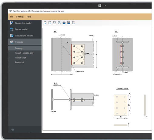
The program creates an advanced and dynamic sketch of the designed connection model, which can also be saved to an editable file in the DXF format.
Reports with the verification result in the RTF or PDF format can be created in four different detailed levels with the option of customizing their scope by the user.

The following types of connections are supported:
SIMPLE group:
-
BEAM-TO-GIRDER simple connection +DXF
-
BEAM-TO-COLUMN simple connection +DXF
-
BEAM SPLICE connection +DXF
END PLATE group:
-
BEAM-TO-COLUMN END PLATE connection +DXF
-
BEAM-TO-BEAM END PLATE connection +DXF
TRUSSES group:
-
TRUSS GUSSET PLATE connection +DXF
-
WELDED TUBULAR TRUSS node +DXF
BASE PLATE group:
-
I-BEAM COLUMN BASE +DXF
-
DOUBLE-BRANCH COLUMN BASE +DXF
-
RECTANGULAR HOLLOW SECTION COLUMN BASE +DXF
-
CIRCULAR HOLLOW SECTION COLUMN BASE +DXF
